Explosion-Proof Switches
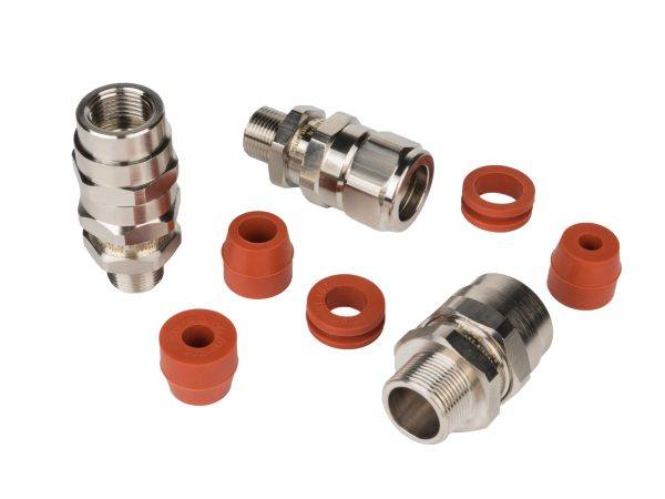 Explosion-Proof Cable Glands
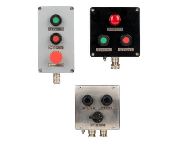 Explosion-Proof Control Stations
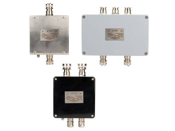 Explosion-Proof Junction Boxes
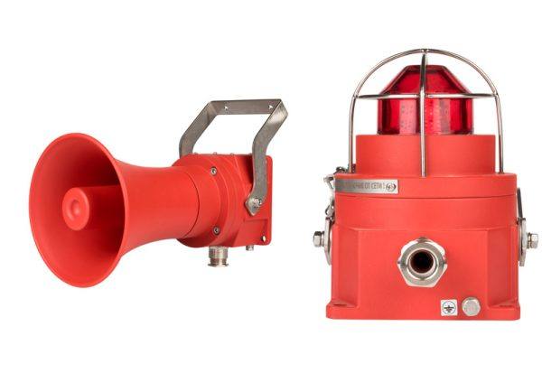 Audible and Visual Alarms
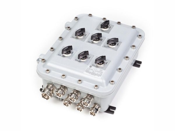 Explosion-Proof Cabinets
 Explosion-Proof Luminaires
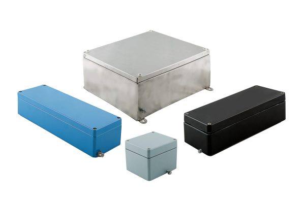 Explosion-Proof and Industrial Enclosures
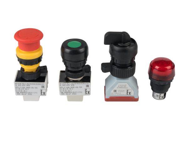 Explosion-Proof Controls
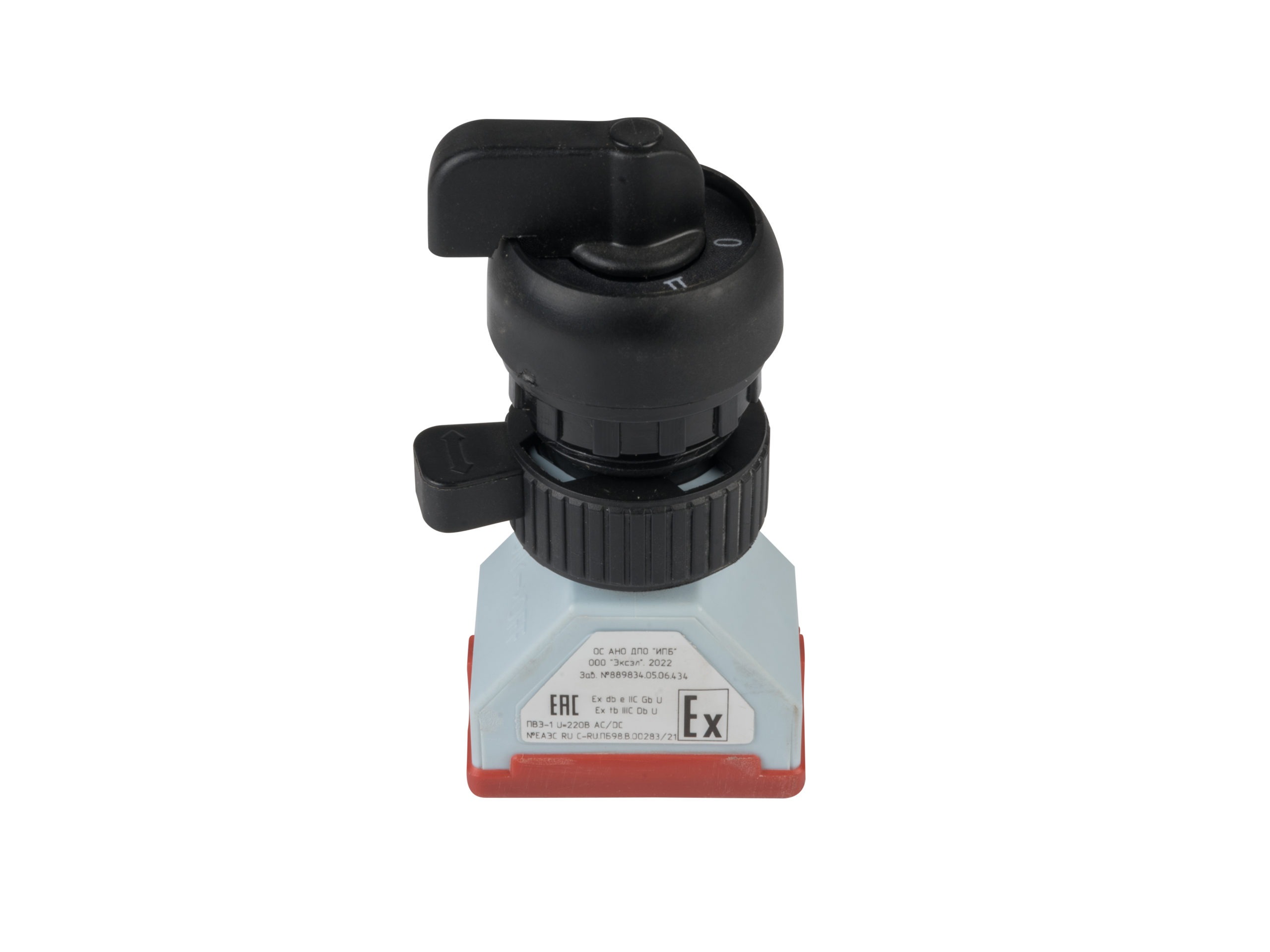
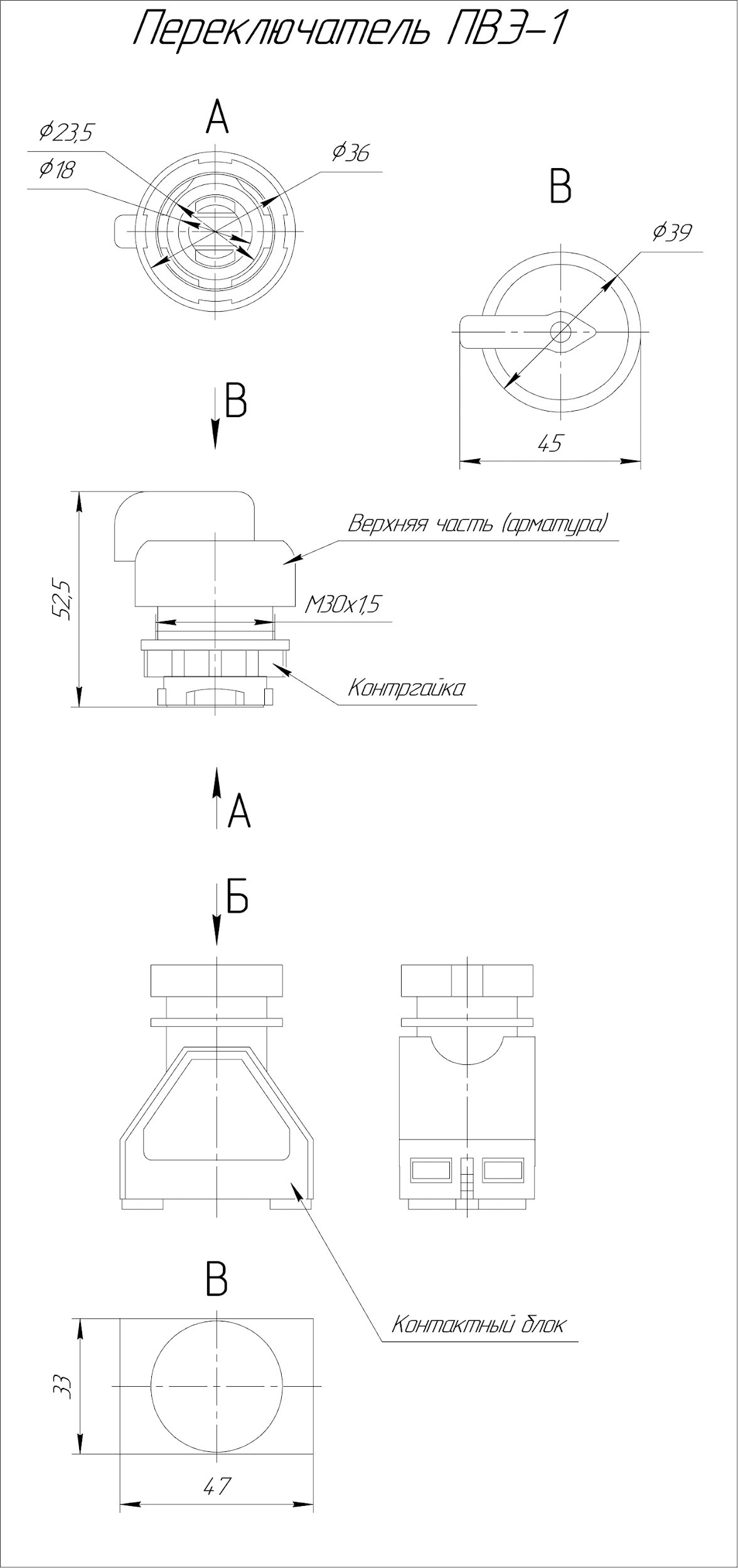
PVE-1 explosion-proof switches are intended for use in low-voltage electrical circuits assembled with explosion-proof enclosures installed indoors or outdoors, as well as on offshore platforms and port terminals, in hazardous areas with explosive atmospheres or combustible dust.
Table 1. Technical Parameters of the PVE-1 Series
| № | Parameter | Value |
| PVE-1 | ||
| 1 | Enclosure Protection Rating (IP) according to GOST 14254-2015 | |
| 1,1 | not installed in the enclosure | IP 20 |
| 1,2 | installed in the enclosure | IP 67 |
| 2 | Operating Temperature, °C: | from -60 to +60 |
| 2.1 | Relative Humidity | 100% at +25°C |
| 3 | Explosion Protection Markings: | |
| 3,1 | Gas Markings: | Ex d e IIC Gb U |
| 3 | Dust Markings: | Ex tb IIIC Db U |
| 4 | Rated Operating Voltage, Ue, V | 12-380 |
| 5 | Rated Current, In, A (AC) | 10 |
| 6 | Frequency of Operations, Cycles/Hour | 3600 |
| 7 | Mechanical Durability, Cycles | 1х106 |
| 8 | Cable Cross-Section, mm2 | 0,75….1,5 |
| 9 | Dimensions | PVE-1:175х47х39 |
| 10 | Weight | PVE-1 – 109 g |


PVE-1 Series
For Explosion-Proof Switches :
PVE – Х1 – Х2 –Х3 –(wX4)– Х5 – Х6 – Х7 … ) where
Х1 – series number 1
Х2 Х3 – type of contact configuration and possible switch positions 01-15:
w (optional) – the symbol is added when ordering a PVE unit with a pre-installed cable;
X4 (optional) – the symbol indicates the cable length in meters when ordering a PVE
with a non-standard cable length (different from 1 m);
X5 – voltage:
AC/DC24-36
AC/DC220-380
X6 – control type:
1 – key switch
2 – 2-pole switch;
3 – 4-pole switch;
Х7 – text (by default, printed on an adhesive thermal label; for individual orders — on a stainless steel nameplate):
1 – (none)
2 – on
3 – off
4 – start
5 – stop
6 – auto
7 – manual
8 – fault
Other inscriptions available upon request.
* If any position such as X1, X2, etc., is not required, use “0”. If several positions at the end of the code (e.g., “options”) are not required, simply finish the code.