Explosion-Proof Stainless Steel Junction Boxes 1Exe KVs
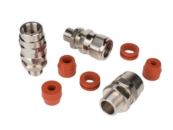 Explosion-Proof Cable Glands
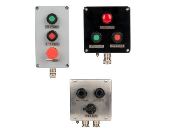 Explosion-Proof Control Stations
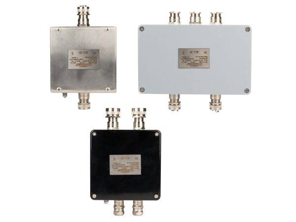 Explosion-Proof Junction Boxes
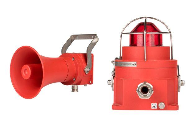 Audible and Visual Alarms
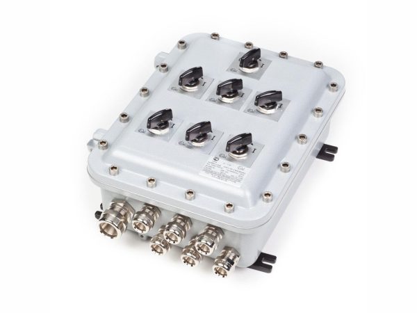 Explosion-Proof Cabinets
 Explosion-Proof Luminaires
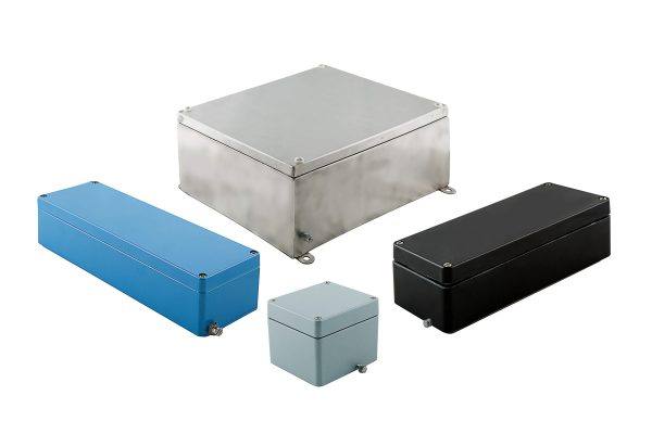 Explosion-Proof and Industrial Enclosures
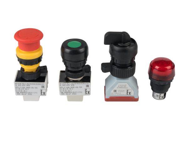 Explosion-Proof Controls
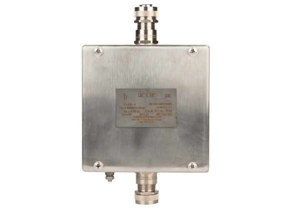
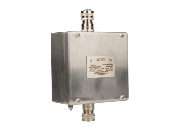
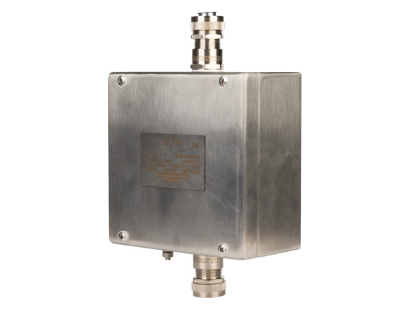
KVs series junction boxes are made of stainless steel and are intended for cable connection and distribution, switching and control of electrical equipment, for indoor and outdoor installation, as well as on offshore platforms and port terminals, in hazardous areas with explosive atmospheres or combustible dust. They can be equipped with various terminals and cable glands, as well as other certified explosion-proof equipment, for example, Pepperl+Fuchs devices such as surge protection equipment, remote I/O components and modules, terminal modules, and FieldConnex modules.
Technical Specifications
| Main Explosion-Proof Markings*: | |
| Gas Markings: | 1Ex e IIC T6…T4 Gb X |
| Gas Markings for Intrinsically Safe Circuits: | 0Ex ia IIC T6…T4 Ga X |
| Dust Markings: | Ex tb IIIC Т85°C… Т135°C Db X |
| Ingress Protection: | IP66/67/68 |
| Rated Voltage: | up to 990 V |
| Rated Current: | up to 500 A |
| Permissible Ambient Temperature: | -60 to +60ºС |
| Climatic Design: | NF1 by default; other options (MU1, U1, W1) on request |
| Material: | stainless steel (304L, 314L) |
| Default Colour: | natural grey brushed metal |


Certificates:
Table of Items
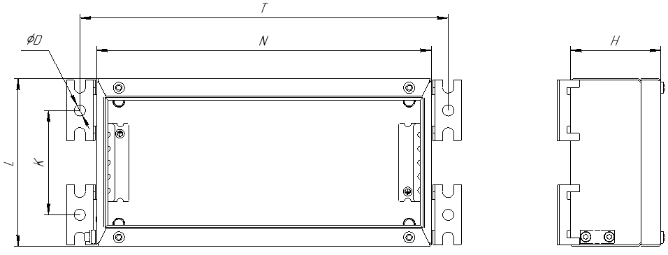
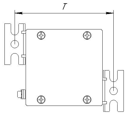
| KV No. | Dimensions | T | K | Weight, kg | D | ||
| N | L | H | |||||
| KVs-1 | 100 | 100 | 61 | 130 | -* | 0,6 | 10 |
| KVs-2 | 150 | 100 | 61 | 180 | -* | 0,8 | 10 |
| KVs-3 | 150 | 150 | 81 | 180 | -* | 1,2 | 10 |
| KVs-4 | 200 | 100 | 61 | 230 | -* | 0,9 | 10 |
| KVs-5 | 200 | 200 | 81 | 230 | -* | 1,8 | 10 |
| KVs-6 | 200 | 200 | 121 | 230 | -* | 2,1 | 10 |
| KVs-7 | 300 | 150 | 81 | 330 | 93,5 | 1,9 | 10 |
| KVs-8 | 300 | 200 | 81 | 330 | 106,5 | 2,6 | 10 |
| KVs-9 | 300 | 200 | 121 | 330 | 106,5 | 2,8 | 10 |
| KVs-10 | 300 | 300 | 121 | 330 | 243,5 | 3,9 | 10 |
| KVs-11 | 300 | 300 | 161 | 330 | 243,5 | 4,3 | 10 |
| KVs-12 | 380 | 380 | 161 | 410 | 323,5 | 161 | 10 |
| KVs-13 | 400 | 150 | 81 | 430 | 93,5 | 81 | 10 |
| KVs-14 | 400 | 200 | 121 | 430 | 143,5 | 121 | 10 |
| KVs-15 | 400 | 300 | 161 | 430 | 243,5 | 5,3 | 10 |
| KVs-16 | 500 | 300 | 161 | 530 | 243,5 | 6,2 | 10 |
| KVs-17 | 500 | 400 | 161 | 530 | 343,5 | 7,2 | 10 |
| KVs-18 | 600 | 200 | 121 | 630 | 143,5 | 5 | 10 |
| KVs-19 | 306 | 306 | 217 | 361 | 217 | 6 | 11 |
| KVs-20 | 458 | 382 | 217 | 437 | 305 | 7,3 | 11 |
| KVs-21 | 762 | 508 | 217 | 564 | 508 | 7,5 | 11 |
| KVs-22 | 860 | 640 | 217 | 696 | 530 | 9 | 11 |
| KVs-23 | 980 | 740 | 217 | 796 | 700 | 10 | 11 |
| KVs-24 | 200 | 150 | 100 | 110 | 270 | 1,59 | 11 |
| KVs-25 | 200 | 200 | 100 | 160 | 270 | 1,91 | 11 |
| KVs-26 | 300 | 400 | 150 | 360 | 370 | 4,79 | 11 |
| KVs-27 | 300 | 300 | 200 | 266 | 376 | 4,64 | 11 |
| KVs-28 | 380 | 260 | 200 | 220 | 450 | 4,86 | 11 |
| KVs-29 | 400 | 200 | 150 | 160 | 470 | 3,71 | 11 |
| KVs-30 | 400 | 300 | 120 | 260 | 470 | 4,4 | 11 |
| KVs-31 | 400 | 400 | 200 | 360 | 470 | 6,64 | 11 |
| KVs-32 | 600 | 400 | 200 | 360 | 670 | 9,03 | 11 |
| KVs-33 | Special Dimensions | ||||||
Highlighted Items are always in stock.
*- For smaller sizes, two brackets are used instead of four.
Ordering Code:
КВХ1 – Х2 – (Х3/N3) – А (Хa/Na) – В (Xb/Nb) – C (Хc/Nc) – D (Xd/Nd) where,
Enclosure Characteristics:
X1 – enclosure material (c – stainless steel);
if an enclosure with explosion protection of the "intrinsically safe circuit" type is required
, the sign "i" should be added,
Х2 – explosion-proof enclosure index (see Table).
Terminal Characteristics:
Х3 – terminal type (cross-section of the connected conductor),
if this terminal is used for a grounding wire, the sign "z».
Screw terminals are installed by default. If spring-type terminals are required, index "P" should be added.
Grey terminals are installed by default. If blue terminals are required, index "B" should be added.
N3 – number of terminals of this type;
Cable Gland Characteristics:
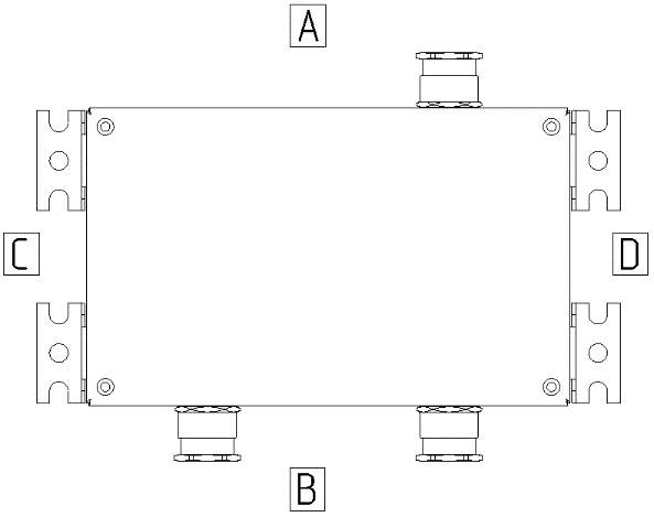
А (Хa/Na) – type and quantity of cable glands on side A (top);
В (Xb/Nb) – type and quantity of cable glands on side B (bottom);
C (Хc/Nc) – type and quantity of cable glands on side C (left);
D (Xd/Nd) – type and quantity of cable glands on side D (right).
For example, an explosion-proof stainless steel enclosure (type KVs-14) with external dimensions of 220×120×90 mm, equipped with five terminals for 2.5 mm2 conductors, ten terminals for 6 mm2 conductors, one grounding terminal for a 4 mm2 conductor, one M16 opening at the bottom of the enclosure, and one VVKm32 metal gland for a non-armoured cable installed at the top of the enclosure, is designated as follows:
KVs–14 – (2.5/5, 6/10, 4z/1) – А (VVKm32/1) – V (M16/1).
Data Sheet:
Appendix – Data Sheet for Enclosures.