Explosion-Proof Control and Indication Stations UMK-A-P
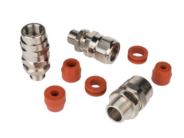 Explosion-Proof Cable Glands
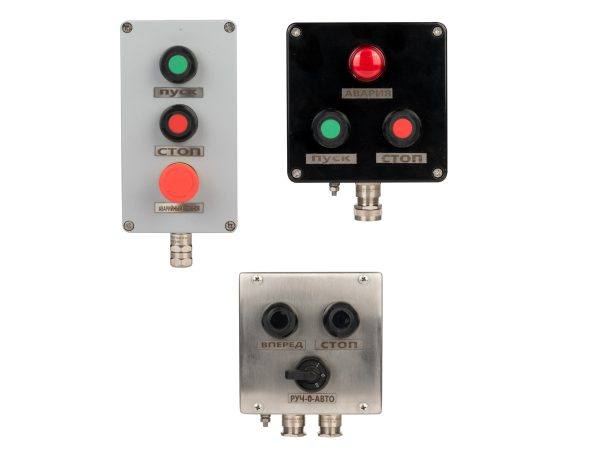 Explosion-Proof Control Stations
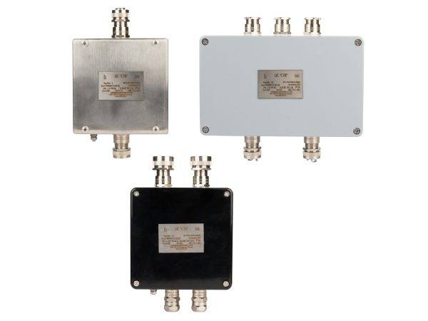 Explosion-Proof Junction Boxes
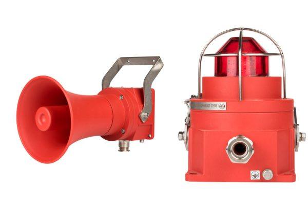 Audible and Visual Alarms
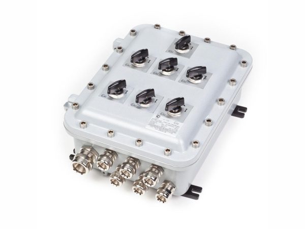 Explosion-Proof Cabinets
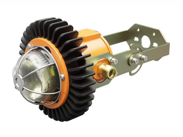 Explosion-Proof Luminaires
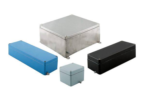 Explosion-Proof and Industrial Enclosures
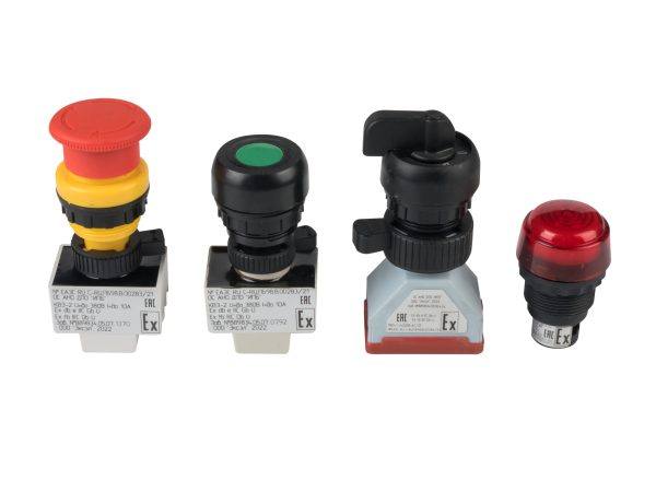 Explosion-Proof Controls
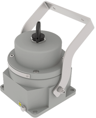
Explosion-proof control stations UMK-A-P are designed for control, indication, connection, and distribution of cables in alarm and signalling systems, for indoor or outdoor installation, in explosion hazardous areas, areas with combustible dust hazards, as well as in areas with possible flame exposure to the equipment.
Technical Specifications
| Explosion Protection Markings: | |
| Gas Markings: | 1Ex db IIC T6…T5 Gb 1Ex db [ia Ga] IIC T6…T5 Gb |
| Dust Markings: | Ex tb IIIC T85 °C…T100°C Db Ex tb [ia Da] IIIC T85°C…T100°C Db |
| Ingress Protection: | IP65/IP66 (IP67 with O-ring seal on request) |
| Rated Voltage AC/DC: | 12DC, 24 DC, 36 DC, 48 DC, 60 DC, 110 AC, 220 AC, 240 AC, 254 AC |
| Rated Current: | 10 to 24 A |
| Permissible Ambient Temperature: | -60 to +60ºС |
| Climatic Design: | NF1 by default; other options (MU1, U1, W1) on request |
| Material: | low-copper aluminium (default) or stainless steel |
| Default Colour: | light grey RAL 7035, other colours on request |
Ordering Code:
UMK-A-P coding for simple single products:
UMK-A – P – (X1/К1/V1/C1) – (X2/N2) – X3(A (Xa/Na) – B (Xb/Nb) – C (Xc/Nc) – D (Xd/Nd)) – X4 – X5 – X6 – X7;
P – designation for “Control Station”;
Pn – stainless steel version.
Controls and Indicators:
(X1/K1/V1/C1) – element designation, contact type, poles, current, and voltage
X1 – lamp type and power:
• KEV – pushbutton
• KEV – mushroom pushbutton
• VEV – control handle for circuit breakers or cam switches
• LEV – indicator lamp
K1 – number and type of contacts for KEV pushbuttons:
• 1NO, 1NC, 2NO, 2NC, 3NO, 3NC, 4NO, 4NC, 1NO/1NC, 2NO/2NC
• Number of poles / rated current for VEV 1, 2, 3 / up to 100 A
V1 – rated voltage: 24 to 660 V/380 V (AC/DC) For LEV lamps: 12 V, 24 V, 36 V, 48 V, 110 V, 220 V
C1 – colour of KEV pushbutton / LEV indicator lamp:
- 0 – none (white/transparent),
- 1 – red,
- 2 – yellow,
- 3 – green,
- 4 – blue,
- 5 – orange,
- 6 – black.
X2 – terminal type
N2 – number of terminals (up to 14 MVK 2.5)
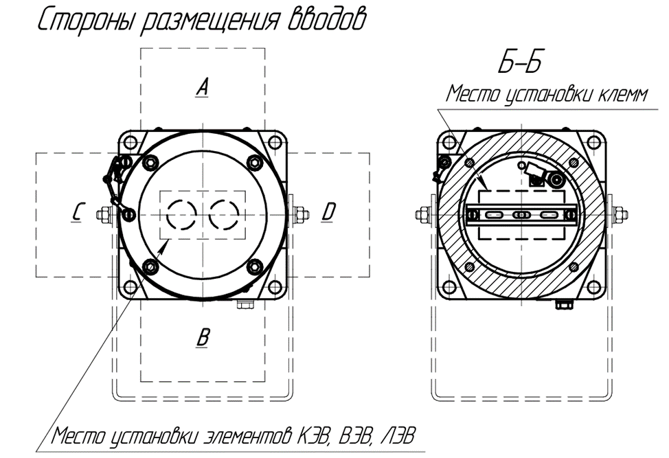
X3 – cable gland characteristics:
• A (Xa/Na) – side A:
type and number of cable glands (one
or two M16; M20; M25 or M32)
• B (Xb/Nb) – side B:
type and number of cable glands (one
or two M16; M20; M25 or M32)
• C (Xc/Nc) – side C:
type and number of cable glands (one
M16; M20; M25 or М32)
• D (Xd/Nd) – side D:
type and number of cable glands (one
M16; M20; M25 or М32)
X4 – fastening options:
• 3 – wall mounting with a support
bracket
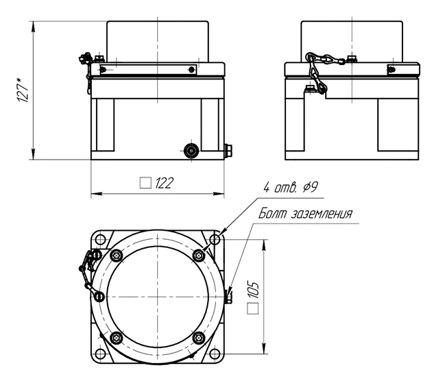
• 4 – mounting holes in the enclosure
(default)
Options:
• X5 – painting the enclosure in a customer-specified RAL colour (default:
grey RAL 7035)
• X6 – nameplate with the customer’s text
(e.g., position designation with project number)
• X7 – visor
UMK-А – P – (KVE-2-12-220-1-1-6\2, PVE-1-01-(220-380)-2\2) – (0/0) – А (VVKm32/1).